Social Share

Saturday 14 November 2015

MLS

Introduction

The MLS is a system of precission approach for landing by instruments and constitutes a kind of an alternative to the ILS system. It provides information about the azimuth, optimal angle of descent and the distance, as well as data about the reverse course in case of an unsuccessful approach. It has several advantages compared to the ILS, for example a greater number of possible executed approaches, a more compact ground equipment, and a potential to use more complicated approach trajectories. However for certain reasons, in particular the advancement of the GPS satelite navigation, was the installation of new devices halted and finally in 1994 completely canceled by the FAA organization. On european airports we can rather seldom come across an MLS.
The MLS provides an accurate landing approach for an aircraft in the area of the final approach, where the path of the final approach isn’t identical with the enlonged runway’s axis. The system works with a microwave beam that is transmitted towards the sector of approach and scans the sector both in the horizontal as well as the verical plane. An aircraft in the approach sector receives the signal and with the help of this beam evaluates it’s location in space. The aircraft’s position is therefore determined both in the horizontal direction of approach and the vertical plane, in whatever point of reach of the scanning beam. Because the microwave technology is radiated into the space of approach in a given time and it’s not spread out over different directions, no signal interruption results from various obstacles or terrain protrusions as it was with the ILS system. The MLS system can thus be situated also in developed areas, where an ILS system couldn’t be set up. An onboard computer enables to solve the approach manoeuvre from a random direction, for variously oriented runways, even along a curved of bend landing trajectory. The MLS system is approved by the ICAO for every three categories of an accurate landing approach.

Basic elements of the MLS

The MLS system is comprised of ground pieces of equipment that are divided into the protractor components, rangefinder components, and the onboard hardware. The information about the angles of the approach course, descent, flare and the course of an unsuccessful approach are aquired through an onboard antenna or the aircraft itself by measuring the time between two passages of an oscillating lobe of a high frequency signal . The distance is determined with the help of an ancillary device, the DME rangefinder. The MLS system further sends with the help of phase modulation and time-division multiplexing additional data, as identification, system status and so on. The ground equipment consists in the basic configuration of an Azimuth Transmitter (AZ) with an added DME rangefinder, perhaps even a more precise DME/P, in close distance of a course transmitter and near an elevation transmitter, see Fig. 1. A scaled up configuration is supplemented with a course transmitter for an unsuccessful approach and a flare transmitter.
MLS components near the runway including beams.Figure 1 – A display of the MLS components and their approximate placement beside the runway.
(figure source: http://oea.larc.nasa.gov/trailblazer/SP-4216/photos/p42a.JPG)

Ground Distance Measuring Equipment (DME)

The rangefinder unit presents a DME which is positioned together with the course transmitter. In connection with requirements of accuracy of the MLS system arose a demand to refine the DME system, which was accomplished with the accurate DME/P rangefinder (along with the DME/W and DME/N). Hence the function of the DME is to provide a pilot information about the distance from a specific point which is essential for pinpoint calculation of the plane’s position in the three-dimensional space.

Ground protractor components

The ground principle of both protractor parts of the MLS system for horizontal and vertical homing of an aircraft is to create levelled emiting diagrams, oscillating at a constant speed in directions „TO‘‘ and „FROM“, and to measure the elapsed time between two passages of an oscillating plane lobe through an onboard MLS antenna.
Scheme of a ground protractor set-up of the MLS system.Figure 2 – Scheme of a ground protractor set-up of the MLS system.
A runway fully equipped with the MLS system contains four transmitters. Two relays supply information about the angle of the azimuth (horizontal) plane and are located face to the runway, along it‘s axis. They are appended with a DME or DME/P rangefinder device, while one of the transmitters is dessignated for the course of approach and the other for the course of an unsuccessful approach. They are positioned 400-600 m from the runway’s threshold. Another two relays transmit angular information for the descent and flare (taking over the function of a descent beacon in the ILS). These are located at a distance of 120-150 m from the runway’s axis, while the transmitter of descent signals is situated 200-300 m from the runway’s threshold and the flare relay 700-1000 m from the beggining of the runway in the direction of approach. If the runway’s equipped with both azimuthal relays, then the relay whose antenna is turned in the direction of an approaching aircraft (the transmitter on the faraway side of the runway) represents an approach course transmitter and the relay close to the approaching aircraft takes over the function of an unsuccessful course transmitter. It’s similar also for the descent and flare relays.

Onboard equipment

  • One or more MLS antenna systems
  • Onboard MLS receiver of signals of the ground protractor devices with a computing system for real time calculation of angular information
  • Interrogator of the DME radio rangefinder
  • Onboard MLS indicator
  • Interconnection of the onboard MLS receiver’s output and the control systems
The onboard equipment has to be able to decode and process functions of the landing approach azimuth including one with a high frequency of regeneration, the reverse azimuth, the angle of descent, and necessary data to accomplish projected flights. Information about the distance is decoded independently. The homing angle is determined by measuring the interval between the reception of the scanning lobes „TO“ and „FROM“. If the equipment is qualified, the receiver has the option of manual or automatic selection of a landing approach trajectory, an angle of descent and a reverse azimuth. Operating in the automatic mode, the selection is made with the aid of information present in the code names of the primary data.

Principle of operation

The MLS system operates at a frequency band of 5031,0 – 5090,7 MHz on two separate channels at a mutual interval of 300 kHz. The protractor part of the MLS system provides continually information about an aircraft’s position relative to the runway both in the vertical and horizontal plane. The rangefinder part enables to measure the distance between an aircraft and the reference points in the approach process. The angular information for the approach course, descent, flare and go-around is determined by measuring the interval between two passages of an oscillating plane lobe through an onboard MLS antenna.
The MLS system is capable to provide coverage of maximum ± 60.0° in the azimuthal (horizontal) plane, whereby a typical device makes use of only ± 40.0° from the runway’s axis in the azimuthal plane for the final approach and ± 20.0° for a missed approach course, see Fig. 3. Of which the minimal ordained proportional homing sector is ± 10.0° from the runway’s axis. Thereafter is the space covered in the vertical plane from 0.9° to 15° with a coverage up to an altitude of 6000 m, for an approach distance of 37 km (see Fig. 4) and to a height of 1500 m and distance of 9,4 km for a missed approach.
An illustration of the horizontal signal’s coverage and it’s oscillation Figure 3 – An illustration of the horizontal signal’s coverage and it’s oscillation.
(figure source: http://accessscience.com/loadBinary.aspx?filename=424150FG0020.gif)
An illustration of the vertical signal’s coverage for various glide slope angles.Figure 4 – An illustration of the vertical signal’s coverage for various glide slope angles.
(figure source: http://www.airresearch.com/Pilots/AIM/Chap1/f0101009.gif)
All data stated below is gradually transmitted on the same frequency with a repetitive frequency:
  • 13 Hz – azimuth (course guide), for systems with the ability to swiftly restore the course information a frequency of 93 Hz is used.
  • 6,5 Hz – missed approach course
  • 39 Hz – elevation
In order to maintain a synchronized timing of the transmission’s individual data blocks, are all parts of the MLS synchronized. Data about the distance is received separately on an interconnected DME channel. Utilizing the MLS data with onboard computers and control systems, it’s possible to carry out a precision approach and landing in similar fashion as with the ILS system, on top with the option to execute curved of broken arched trajectories of approach and automatic landings. All parts of the MLS system include their own monitor circuits that in the case of an out of tolerance deviation of some outer MLS parameters switch the devices on a back up array. In case of a long-time deviation the pilot gives notice about the change to the traffic control.
The exact information about an aircraft’s position enables to perform more complicated procedures, as flying along a curved glide slope or using multiple glide slopes. An appropriate precision allows to improve the air traffic flow on busy airports through curved fly paths. ICAO quantifies the required system’s accuracy as stated in the ICAO regulations Annex 10.
The complete accuracy limits include all errors caused by the onboard equipment and radio waves broadcast. They’re specified for a part of the flight path containing the reference approach altitude and reference missed approach height for a go-around. The reference landing height is 15 m (50 ft).


ELTs

Emergency Beacons


imageThere are three types of beacons used to transmit distress signals, EPIRBs (for maritime use), ELTs (for aviation use), and PLBs (used for land-based applications).


Emergency Locator Transmitters (ELTs)

imageELTs were the first emergency beacons developed and most U.S. civil aircraft are required to carry them. ELTs were intended for use on the 121.5 MHz frequency to alert aircraft flying overhead. Obviously, a major limitation to these is that another aircraft must be within range and listening to 121.5 MHz to receive the signal. One of the reasons the Cospas-Sarsat system was developed was to provide a better receiving source for these signals. Another reason was to provide location data for each activation(something that overflying aircraft were unable to do).
Different types of ELTs are currently in use. There are approximately 170,000 of the older generation 121.5 MHz ELTs in service. Unfortunately, these have proven to be highly ineffective. They have a 97% false alarm rate, activate properly in only 12% of crashes, and provide no identification data. In order to fix this problem 406 MHz ELTs were developed to work specifically with the Cospas-Sarsat system. These ELTs dramatically reduce the false alert impact on SAR resources, have a higher accident survivability success rate, and decrease the time required to reach accident victims by an average of 6 hours. 
Presently, most aircraft operators are mandated to carry an ELT and have the option to choose between either a 121.5 MHz ELT or a 406 MHz ELT. The Federal Aviation Administration has studied the issue of mandating carriage of 406 MHz ELTs. The study indicates that 134 extra lives and millions of dollars in SAR resources could be saved per year. The only problem is that 406 MHz ELTs currently cost about $1,500 and 121.5 MHz ELTs cost around $500. It's easy to see one reason for the cost differential when you look at the numbers. However, no one can argue the importance of 406 MHz ELTs and the significant advantages they hold.
For more information on the differences between 121.5 MHz Beacons and 406 MHz beacons click to view a Comparison.
Due to the obvious advantages of 406 MHz beacons and the significant disadvantages to the older 121.5 MHz beacons, the International Cospas-Sarsat Program have made a decision to phaseout 121.5 MHz satellite alerting on February 1st, 2009.  All pilots are highly encouraged both by NOAA and by the FAA to consider making the switch to 406!

frequency band table

Frequency or frequency bandSubpartClass of stationRemarks
108.000 MHzQRadionavigation land test
108.000-108.050 MHzQVHF omni-rangeVHF omni-range (VOR) [87.475(b)(5)]
108.050 MHzQRadionavigation land test
108.050-108.100 MHzQVHF omni-rangeVHF omni-range (VOR) [87.475(b)(5)]
108.100 MHzQRadionavigation land test
108.100-108.150 MHzQLocalizerILS localizer [87.475(b)(4)]
108.150 MHzQRadionavigation land test
108.150-111.950 MHzQLocalizerILS localizer [87.475(b)(4)]
111.950-117.950 MHzQVHF omni-rangeVHF omni-range (VOR) [87.475(b)(5)]
118.000-121.400 MHzOAircraft (Air carrier and Private), Airport control tower, Automatic weather observation25 kHz channel spacing
121.500 MHzGHIJK,MOAircraft (Air carrier and Private), Aeronautical advisory (unicom), Aeronautical enroute, Flight test, Aviation support, Airport control tower, Aeronautical multicom, Civil Air PatrolEmergency and distress [87.195]. Maritime Radiodetermination [80.375]
121.600-121.925 MHzOLQAircraft (Air carrier and Private), Airport control tower, Aeronautical utility mobile, Radionavigation land test25 kHz channel spacing
121.950 MHzKAviation support
121.975 MHzFPrivate aircraft only, Automatic weather observationAir traffic control operations
122.000 MHzFAircraft (Air carrier and Private)Air carrier and private aircraft enroute flight advisory service provided by FAA
122.025 MHzFPrivate aircraft only, Automatic weather observationAir traffic control operations
122.050 MHzFAircraft (Air carrier and Private)Air traffic control operations
122.075 MHzFPrivate aircraft only, Automatic weather observationAir traffic control operations
122.100 MHzFOAircraft (Air carrier and Private), Airport control towerAir traffic control operations
122.125-122.675 MHzFPrivate aircraft onlyAir traffic control operations; 25 kHz spacing
122.700 MHzGLAircraft (Air carrier and Private), Aeronautical advisory (unicom), Aeronautical utility mobileUnicom at airports with no control tower; Aeronautical utility stations
122.725 MHzGLPrivate aircraft only, Aeronautical advisory (unicom), Aeronautical utility mobileUnicom at airports with no control tower; Aeronautical utility stations
122.750 MHzFPrivate aircraft onlyPrivate fixed wing aircraft air-to-air communications
122.775 MHzKAircraft (Air carrier and Private), Aviation support
122.800 MHzGLAircraft (Air carrier and Private), Aeronautical advisory (unicom), Aeronautical utility mobileUnicom at airports with no control tower; Aeronautical utility stations
122.825 MHzIAircraft (Air carrier and Private), Aeronautical enrouteDomestic VHF
122.850 MHzHK,Aircraft (Air carrier and Private), Aeronautical multicom, Aviation support
122.875 MHzIAircraft (Air carrier and Private), Aeronautical enrouteDomestic VHF
122.900 MHzF, H, LMAircraft (Air carrier and Private), Aeronautical search and rescue, Aeronautical multicom, Aeronautical utility mobile
122.925 MHzHPrivate aircraft only, Aeronautical multicom
122.950 MHzGLPrivate aircraft only, Aeronautical advisory (unicom), Aeronautical utility mobileUnicom at airports with full-time control tower [87.217]; Aeronautical utility stations
122.975 MHzGLPrivate aircraft only, Aeronautical advisory (unicom), Aeronautical utility mobileUnicom at airports with no control tower; Aeronautical utility stations
123.000 MHzGLAircraft (Air carrier and Private), Aeronautical advisory (unicom), Aeronautical utility mobileUnicom at airports with no control tower; Aeronautical utility stations
123.025 MHzFPrivate aircraft onlyHelicopter air-to-air communications; Air traffic control operations
123.050 MHzGLPrivate aircraft only, Aeronautical advisory (unicom), Aeronautical utility mobileUnicom at airports with no control tower; Aeronautical utility stations
123.075 MHzGLPrivate aircraft only, Aeronautical advisory (unicom), Aeronautical utility mobileUnicom at airports with no control tower; Aeronautical utility stations
123.100 MHzM, OAircraft (Air carrier and Private), Airport control tower, Aeronautical search and rescue
123.125 MHzJAircraft (Air carrier and Private), Flight testItinerant
123.150 MHzJAircraft (Air carrier and Private), Flight testItinerant
123.175 MHzJAircraft (Air carrier and Private), Flight testItinerant
123.200 MHzJAircraft (Air carrier and Private), Flight test
123.225 MHzJAircraft (Air carrier and Private), Flight test
123.250 MHzJAircraft (Air carrier and Private), Flight test
123.275 MHzJAircraft (Air carrier and Private), Flight test
123.300 MHzKAircraft (Air carrier and Private), Aviation support
123.325 MHzJAircraft (Air carrier and Private), Flight test
123.350 MHzJAircraft (Air carrier and Private), Flight test
123.375 MHzJAircraft (Air carrier and Private), Flight test
123.400 MHzJAircraft (Air carrier and Private), Flight testItinerant
123.425 MHzJAircraft (Air carrier and Private), Flight test
123.450 MHzJAircraft (Air carrier and Private), Flight test
123.475 MHzJAircraft (Air carrier and Private), Flight test
123.500 MHzKAircraft (Air carrier and Private), Aviation support
123.525 MHzJAircraft (Air carrier and Private), Flight test
123.550 MHzJAircraft (Air carrier and Private), Flight test
123.575 MHzJAircraft (Air carrier and Private), Flight testItinerant
123.6-128.8 MHzOAircraft (Air carrier and Private), Airport control tower, Automatic weather observation25 kHz channel spacing
128.825-132.000 MHzIAircraft (Air carrier and Private), Aeronautical enrouteDomestic VHF; 25 kHz channel spacing
132.025-135.975 MHzOAircraft (Air carrier and Private), Airport control tower, Automatic weather observation25 kHz channel spacing
136.000-136.075 MHzOSAircraft (Air carrier and Private), Airport control tower, Automatic weather observationAir traffic control operations
136.100 MHzReserved for future unicom or AWOS
136.125-136.175 MHzOSAircraft (Air carrier and Private), Airport control tower, Automatic weather observationAir traffic control operations
136.200 MHzReserved for future unicom or AWOS
136.225-136.250 MHzOSAircraft (Air carrier and Private), Airport control tower, Automatic weather observationAir traffic control operations
136.275 MHzReserved for future unicom or AWOS
136.300-136.350 MHzOSAircraft (Air carrier and Private), Airport control tower, Automatic weather observationAir traffic control operations
136.375 MHzReserved for future unicom or AWOS
136.400-136.450 MHzOSAircraft (Air carrier and Private), Airport control tower, Automatic weather observationAir traffic control operations
136.475 MHzReserved for future unicom or AWOS
136.500-136.600 MHzIAircraft (Air carrier and Private), Aeronautical enrouteDomestic VHF
136.625 MHzIAircraft (Air carrier and Private), Aeronautical enrouteDomestic VHF
136.650 MHzIAircraft (Air carrier and Private), Aeronautical enrouteDomestic VHF
136.675 MHzIAircraft (Air carrier and Private), Aeronautical enrouteDomestic VHF
136.700 MHzIAircraft (Air carrier and Private), Aeronautical enrouteDomestic VHF
136.725 MHzIAircraft (Air carrier and Private), Aeronautical enrouteDomestic VHF
136.750 MHzIAircraft (Air carrier and Private), Aeronautical enrouteDomestic VHF
136.775 MHzIAircraft (Air carrier and Private), Aeronautical enrouteDomestic VHF
136.800 MHzIAircraft (Air carrier and Private), Aeronautical enrouteDomestic VHF
136.825 MHzIAircraft (Air carrier and Private), Aeronautical enrouteDomestic VHF
136.850 MHzIAircraft (Air carrier and Private), Aeronautical enrouteDomestic VHF
136.875 MHzIAircraft (Air carrier and Private), Aeronautical enrouteDomestic VHF
136.900 MHzIAircraft (Air carrier and Private), Aeronautical enrouteDomestic VHF
136.925 MHzIAircraft (Air carrier and Private), Aeronautical enrouteDomestic VHF
136.950 MHzIAircraft (Air carrier and Private), Aeronautical enrouteDomestic VHF
136.975 MHzIAircraft (Air carrier and Private), Aeronautical enrouteDomestic VHF
This chart derived from section 87.173 of the F.C.C. Rules.

Airband

his article is about the radio spectrum used in aviation. For bands named Air, see Air 
A typical aircraft VHF radio. The display shows an active frequency of 123.5MHz and a standby frequency of121.5 MHz. The two are exchanged using the button marked with a double-headed arrow. The tuning control on the right only affects the standby frequency.
Airband or Aircraft band is the name for a group of frequencies in the VHF radio spectrum allocated to radio communication in civil aviation, sometimes also referred to asVHF, or phonetically as "Victor". Different sections of the band are used for radionavigational aids and air traffic control.
In most countries a license to operate airband equipment is required and the operator is tested on competency in procedures, language and the use of the phonetic alphabet.

Spectrum usage

Antenna array at Amsterdam Airport Schiphol
The VHF airband uses the frequencies between 108 and 137 MHz. The lowest 10 MHz of the band, from 108–117.95 MHz, is split into 200 narrow-band channels of 50 kHz. These are reserved for navigational aids such as VOR beacons, and precision approach systems such as ILS localizers.
As of 2012, most countries divide the upper 19 MHz into 760 channels for amplitude modulation voice transmissions, on frequencies from 118–136.975 MHz, in steps of 25 kHz. In Europe, it is becoming common to further divide those channels into three (8.33 kHz channel spacing), potentially permitting 2,280 channels. Some channels between 123.100 and 135.950 are available in the US to other users such as government agencies, commercial company advisory, search and rescue, military aircraft, glider and ballooning air-to-ground, flight test and national aviation authority use. A typical transmission range of an aircraft flying at cruise altitude (35,000 ft (10,668 m)), is about 200 mi (322 km) in good weather conditions.

Other bands

Aeronautical voice communication is also conducted in other frequency bands, including satellite voice on Inmarsat and high frequency voice in the North Atlantic and remote areas. Military aircraft also use a dedicated UHF-AM band from 225.0–399.95 MHz for air-to-air and air-to-ground, including air traffic control communication. This band has a designated emergency and guard channel of 243.0 MHz.
Some types of navaids, such as non-directional beacons and Distance Measuring Equipment, do not operate on these frequencies; in the case of NDBs, the low frequency andmedium frequency bands are used between 190–415 kHz and 510–535 kHz. The ILS glide path operates in the UHF frequency range of 329.3–335.0 MHz, and DME also uses UHF from 962–1150 MHz.

Channel spacing

Channel spacing for voice communication on the airband was originally 200 kHz until 1947, providing 70 channels from 118 to 132 MHz. Some radios of that time provided receive-only coverage below 118 MHz for a total of 90 channels. From 1947–1958 the spacing became 100 kHz; from 1954 split once again to 50 kHz and the upper limit extended to 135.95 MHz (360 channels), and then to 25 kHz in 1972 to provide 720 usable channels. On 1 January 1990 the frequencies between 136.000 and 136.975 MHz were added, resulting in 760 channels.
Increasing air traffic congestion has led to further subdivision into narrow-band 8.33 kHz channels in the ICAO European region; all aircraft flying above Flight Level 195 are required to have communication equipment for this channel spacing. Outside of Europe, 8.33 kHz channels are permitted in many countries but not widely used as of 2012.
The emergency communication channel 121.5 MHz is the only channel that retains 100 kHz channel spacing in the US; there are no channel allocations between 121.4 and 121.5 or between 121.5 and 121.6

Modulation

Aircraft communications radio operations worldwide use amplitude modulation, predominantly A3E double sideband with full carrier on VHF and UHF, and J3E single sideband with suppressed carrier on HF. Besides being simple, power-efficient and compatible with legacy equipment, AM and SSB permit stronger stations to override weaker or interfering stations. Additionally, this method does not suffer from the capture effectfound in FM. Even if a pilot is transmitting, a control tower can "talk over" that transmission and other aircraft will hear a somewhat garbled mixture of both transmissions, rather than just one or the other. Even if both transmissions are received with identical signal strength, a heterodyne will be heard where no such indication of blockage would be evident in an FM system.
Alternative analog modulation schemes are under discussion, such as the "CLIMAX" multi-carrier system and offset carrier techniques to permit more efficient utilization of spectrum.

Audio properties

The audio quality in the airband is limited by the RF bandwidth used. In the newer channel spacing scheme, the largest bandwidth of an airband channel might be limited to 8.33 kHz, so the highest possible audio frequency is 4.165 kHz. In the 25 kHz channel spacing scheme, an upper audio frequency of 12.5 kHz would be theoretically possible. However, most airband voice transmissions never actually reach these limits. Usually, the whole transmission is contained within a 6 kHz to 8 kHz bandwidth, corresponding to an upper audio frequency of 3 kHz to 4 kHz. This frequency, while low compared to the top of the human hearing range, is sufficient to convey speech. Different aircraft, control towers and other users transmit with different bandwidths and audio characteristics.

Digital radio

A switch to digital radios has been contemplated, as this would greatly increase capacity by reducing the bandwidth required to transmit speech. Other benefits from digital coding of voice transmissions include decreased susceptibility to electrical interference and jamming. The change-over to digital radio has yet to happen, partly because the mobility of aircraft necessitates complete international cooperation to move to a new system and also the time implementation for subsequent changeover. Another factor delaying the move to any digital mode is the need to retain the ability for one station to override another in an emergency.

Unauthorised use

It is illegal in most countries to transmit on the Airband frequencies without a suitable license, although an individual license may not be required, for instance in the US where aircraft stations are "licensed by rule.". Many countries' regulations also restrict communications in the airband. For instance, in Canada, airband communications are limited to those required for "the safety and navigation of an aircraft; the general operation of the aircraft; and the exchange of messages on behalf of the public. In addition, a person may operate radio apparatus only to transmit a non-superfluous signal or a signal containing non-profane or non-obscene radiocommunications."
Listening to airband frequencies without a license is also an offence in some countries, including the UK, though enforcement may vary. Such activity has been the subject of international situations between governments when tourists bring airband equipment into countries which ban the possession and use of such equipment.

Airport Runway Numbering

When you leave the comforts of home and familiar streets and roadways and enter your favorite airport, you’re likely to encounter strange words, devices, and methods of doing things – at least they may seem strange to the uninitiated. Once you learn the reasons for the way airports operate, build, and function, these once strange concepts begin to make perfect sense. The airport runway numbering system is one of those things.
Jets in Airport
Jets in our hangars at FXE, Ft. Lauderdale Executive Airport.

Airport Runway Numbering Basics

There’s one word that can be said to describe any successful airport in the world: orderly. Airports have a lot of rules and regulations to follow. Without these rules, regulations, and organization, there would likely be chaos in the air and on the ground. That’s one reason why there are so many similarities in airports, large and small, around the world.
airport runway
An airport runway framed by the sea.
There’s a system in play – one that works. Consistent airport runway numbering in airports everywhere gives pilots from all nationalities commonality when landing and taking off. Most airports follow the exact same runway numbering system, leaving little room for confusion, misunderstandings, or mistakes at critical times.

How are Runway Numbers Assigned?

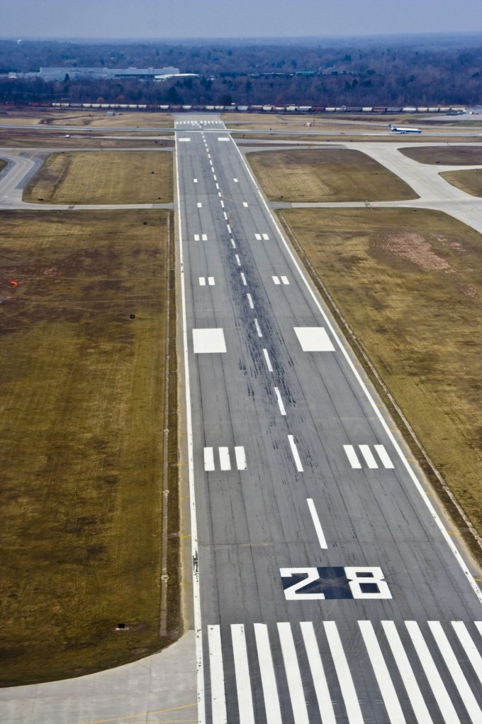
Plainly put, airport runways are numbered according to compass bearings. This means runway numbers are based on the compass with 360 representing north, 90 representing east, 180 representing south, and 270 representing west. Runways are numbered between 01 and 36.
numbered aiport runway
Aerial view of a numbered airport runway.
For runway headings, the last number is dropped and each individual number is pronounced. For instance, a compass heading of 310 degrees would read 31 and be pronounced as three one.
For the sake of simplicity, the FAA rounds headings to the nearest ten so even if the heading is 308 degrees, the runway would be called three one instead.
Since most runways are oriented to take advantage of prevailing winds to assist in takeoffs and landings, they can be used either direction. This is why most runways have two numbers. The second number differs by 18 or 180 degrees.

Busy Airports and Runway Numbering

Some airports are busier than others. Airports that have two parallel runways going in the same direction, they are designated as the left or right runway with an L or R. In this case, runway 31 would be called 31R or 31L. If there are three parallel runways, the designation of C will be assigned to the runway in the center. In this case you would have 31L, 31R, and 31C.
plane at lukla
Plane on the runway at the Tenzing-Hillary airport Lukla – Nepal, Himalayas.
Exceptionally busy airports like ATL in Atlanta and LAX in Los Angeles may have more than three runways parallel to each other. In these instances, even though all runways have the same heading, the number for some of the runways is shifted by ten degrees, making for a one-digit difference.
In the case of DFW (Dallas-Fort Worth) there are five runways with the same heading. Those on the east side of the airport have the traditional L, R, C designations according to standard runway numbers, while those located to the  west have been increased by 10 degrees while utilizing the L and R designations.
Presidential Aviation offers concierge private charter jet services to various airports around the world. Please feel free to call us with any questions you have or to book your next private charter flight today.

VASI and PAPI

A PAPI and a VASI are very similar in the the information they provide. The only functional differences between the VASI and PAPI is that the VASI has the red over the white, the PAPI the white actually goes to the right of the red, and the PAPI offers higher precision (or more glideslopes depending how you look at it a larger airliner with a high cockpit may elect to fly a slightly higher glidepath). The concept is the same though.
VASI looks like this: enter image description here
Usage:
As the saying goes,
Red over White, you're alright. (on glidepath)
Red over Red, you're dead. (too low)
White over White, you're out-of-sight (too high)
enter image description here
PAPI like this: enter image description here
A regular VASI only offers one glide slope and is designed for an aircraft where the cockpit isn't so high up. However, there is a such thing as two-light PAPI, and a three-bar VASI. So either of them can really be tailored to fit the costs and types of aircraft flying to that airport.
In the case of a four-bar PAPI it is higher precision. Since the PAPI systems uses a narrower beam of light you must fly the glide path more precisely than the VASI to stay on the beam. The PAPI, with its extra lights, forewarns you when you are drifting from the desired glide path.
enter image description here
So one red light would indicate slightly above glide slope, two and two would indicate the normal glide slope, and three red lights would indicate slightly below the glide slope on a 4-bar PAPI. A Three bar VASI works in similar fashion except there are only two glide paths with two reds being the lower, two whites the higher.
enter image description here